For bugs and new features, use the issue tracker located at GitHub.
Also try the chat room!

 What is 192.168.0.1
A default IP used by d link, netgear and other popular router manufacturers to find themselves over the network is 192.168.0.1 IP. Users can enter this address into the address bar of their favorite web browser on their computer to get access to the router settings page. There they can change the default password of the router, security settings and Wi-Fi settings of their network. Even they can monitor the connection of their router to the network, reset the connection settings and router or change the firewall settings on the settings webpage. People do not need an active internet connection to access their router settings page. The only thing they need to do is typing the IP address used by their router for administration. The address could vary depending on the router manufacturer.
How can people find the router IP address
People need to perform the following steps to check if the router is using the above mentioned private IP address.
How to change the password of router
It is very important to change the password of router so that no one will be able to access as well as configure the router. People should make sire to note down the username and password. Here are the steps they need to follow for changing the router password.
People should make sure that the password is strong. They can even use online password generator to make the password of router stronger. Once they found the IP address and changed the password, they can configure router settings. They can make some adjustments such as modifying LAN configurations, protection and Wi-Fi connections. Users of routers will feel good when they come to know that they can also control specific configurations of router.

 I can't use Helix toolkit to viewport multiple model part at the same time
Hi Everyone,
I've got an existing Winsform application that model a multi-joint robotic arm, that allows the user to use a trackbar to rotate each joint for a certain degree (snipping of the winsform app below).
Since I've worked out the TranslateTransform and RotateTransform relationship in 2D drawing, I did like to convert it to 3D. I heard that helix toolkit is very good at 3D modelling things. Since I never used it before, so I would like to give helix toolkit a try. What I'm doing is draw the robot arm in wpf and use elementhost to host the drawing in winsform, and in the end aim to achieve the same results as above but in 3D. Currently I applied the same logic I used for the 2D modelling, but with set rotation angle and translation length, as well as I'm trying to get 2 joints connected.
Yet when I run my code, instead of both joints being display (similar to picture above), only 1 joint is present (as shown in picture below).
I don't understands what I did wrong, and since there is very limited documentation available I can't debug and solve the problem myself. So I hope to seek help and solution here.
below is my code:
using System;

[SharpDX] Why does my model look better when using the deferred RenderTechnique instead of e.g. Blinn/Phong
Hello everyone,
When visualizing geometry in the sharpDX viewport, I noticed that all the edges are very jagged and not smooth at all.
Blinn Rendering
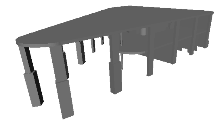
Deferred Rendering

This got a lot better when switching to the deferred rendering.
Is this normal? Is there maybe a way to improve the anti aliasing for the default rendering that I'm not aware of?

UnProject extension method in Viewport3DX

Texture coordinates from ObjReader
Lolligeir wrote at 2013-03-22 18:08:
I am reading some obj files for a ray tracer and I have managed to read the Points of each triangle and the normals but the texture coordinate don´t seem to be working correctly. This is how I am reading the file:
            ObjReader r = new ObjReader();
            Model3DGroup model = r.Read(modelUrl);
            GeometryModel3D gm1 = (GeometryModel3D)model.Children[0];
            MeshGeometry3D mg1 = (MeshGeometry3D)gm1.Geometry;
            Vector3DCollection normals = mg1.Normals;
            System.Windows.Media.PointCollection textureCoordinates = mg1.TextureCoordinates;
            System.Windows.Media.Int32Collection indices = mg1.TriangleIndices;
            Point3DCollection points = mg1.Positions;


            for (int index = 0; index < indices.Count; index += 3)
            {
                Point3D p0 = points[indices[index]];
                Point3D p1 = points[indices[index + 1]];
                Point3D p2 = points[indices[index + 2]];

                Vector3D n0 = normals[indices[index]];
                Vector3D n1 = normals[indices[index + 1]];
                Vector3D n2 = normals[indices[index + 2]];

                System.Windows.Point t0 = textureCoordinates[indices[index]];
                System.Windows.Point t1 = textureCoordinates[indices[index + 1]];
                System.Windows.Point t2 = textureCoordinates[indices[index + 2]];
}
The obj file I have been using (Removed text after vertices to get the objReader to read it) : http://cs.wellesley.edu/~cs307/tw/objects/cube-textures.obj
Best regards,
Viktor

 How to change material property of an imported model3D ?
I'm trying to change the color of a model3D that has been previously imported from an STL file like this:
CurrentModel = HelixToolkit.Wpf.ModelImporter.Load(Path);
where CurrentModel is a model3D. The default color for stl file is blue.
If I want to change its material properties, it's nesserary to use a GeometryModel3D...
var GeoModel = CurrentModel as GeometryModel3D
Then material properties are enabled ...
GeoModel.Material = Materials.Gray;
To add this model to my view, I create a ModelUIElement3D...
ModelUIElement3D ModelUI = new ModelUIElement3D(); and add it ...
ModelUI.Model = geoModel;
Next step should be to add the ModelUIElement3D to the view...
view.Children.Add(ModelUI);
But that doesn't work...
Any ideas ?
Thanks
Lionel
How to access different component from .3ds file
GhufranZahidi wrote at 2012-11-20 10:04:
Hi
I want to access multiple component from .3ds file by name and try to move particular component, is it possible if yes then give method name, please reply

HelixVisual3d not updating after created
I'm need to show a circular torus on the viewport. The closest option I found was the HelixVisual3D, but it has open ends. So I tried to create my own class to draw this, with a HelixVisual3D and two thin cones to close the ends. I used the classes from the Building Demo as reference, so I came up with this:
public class TorusVisual3D : UIElement3D
{
public static readonly DependencyProperty AngleProperty = DependencyPropertyEx.Register("Angle", 90, (s, e) => s.AppearanceChanged());
public static readonly DependencyProperty RadiusProperty = DependencyPropertyEx.Register("Radius", 0.35, (s, e) => s.AppearanceChanged());
public static readonly DependencyProperty DiameterProperty = DependencyPropertyEx.Register("Diameter", 0.1, (s, e) => s.AppearanceChanged());
private GeometryModel3D torus = new GeometryModel3D();
private GeometryModel3D cap1 = new GeometryModel3D();
private GeometryModel3D cap2 = new GeometryModel3D();
public TorusVisual3D()
{
AppearanceChanged();
Model3DGroup model = new Model3DGroup();
model.Children.Add(this.torus);
model.Children.Add(this.cap1);
model.Children.Add(this.cap2);
this.Visual3DModel = model;
}
public double Angle
{
get
{
return (double)this.GetValue(AngleProperty);
}
set
{
this.SetValue(AngleProperty, value);
}
}
public double Radius
{
get
{
return (double)this.GetValue(RadiusProperty);
}
set
{
this.SetValue(RadiusProperty, value);
}
}
public double Diameter
{
get
{
return (double)this.GetValue(DiameterProperty);
}
set
{
this.SetValue(DiameterProperty, value);
}
}
private void AppearanceChanged()
{
Material mat = MaterialHelper.CreateMaterial(Utils.GetRandomColor());
HelixVisual3D h = new HelixVisual3D();
h.Origin = new Point3D(0, 0, 0);
h.Diameter = Diameter;
h.Turns = Angle / 360.0;
h.Radius = Radius;
h.Length = 0;
h.BackMaterial = mat;
h.Material = mat;
h.UpdateModel();
this.torus = h.Model;
MeshBuilder cap1Builder = new MeshBuilder(false, false);
Point3D p1 = new Point3D(0, Radius, 0);
cap1Builder.AddCone(p1, new Vector3D(0, 1, 0), h.Diameter / 2, h.Diameter / 2, 0.0001, true, true, 40);
this.cap1.Material = MaterialHelper.CreateMaterial(Colors.Yellow);
this.cap1.Geometry = cap1Builder.ToMesh();
MeshBuilder cap2Builder = new MeshBuilder(false, false);
Point3D p2 = new Point3D(-1, 0, 0);
cap2Builder.AddCone(p2, new Vector3D(1, 0, 0), h.Diameter / 2, h.Diameter / 2, 0.0001, true, true, 40);
this.cap2.Material = MaterialHelper.CreateMaterial(Colors.Red);
this.cap2.Geometry = cap2Builder.ToMesh();
}
}
To draw it I'm using the following code:
TorusVisual3D t = new TorusVisual3D();
t.Angle = m_angle;
t.Radius = m_radius1;
t.Diameter = m_radius2 * 2.0;
t.Transform = new TranslateTransform3D(0, 0, 0);
ModelVisual3D model = new ModelVisual3D();
model.Children.Add(t);
var container = new ContainerUIElement3D();
container.Children.Add(model);
viewport.Children.Add(container);
The problem is that the Helix is drawn with the default values (Radius=0.35, Diameter=0.1 and Angle=90) and is never updated again. No matter what values I set on the Properties, it stays the same. The both cylinder are updated correctly, just the Helix isn't.
What am I'm doing wrong?
Thanks in advance,
Rodrigo
Storyboard animation
xyxa wrote at 2012-07-14 15:56:
Thanks so much for very useful toolkit.
But unfortunately I could not create a storyboard animation via Blend for any MeshElement3D. It's strange, because I can create such animation for ModelVisual3D. What is the reason for this behavior and Is there any ways to solve it?
Customer support service by UserEcho