For bugs and new features, use the issue tracker located at GitHub.
Also try the chat room!

 UIElement Visual3DModel behaves differently than MeshGeometryVisual3D
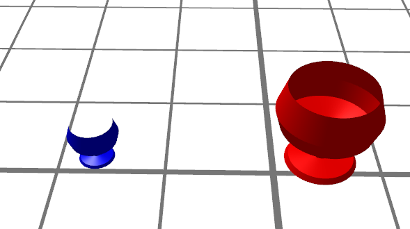
Create a revolve object and display it on the 3D view port. Since I need the object to be clickable, I am adding it using the UIElement example (changed it to have the rotation instead of the sphere). This is partially achieved, this is, the object displays and I can click on it (and have a desired event), but the object does not render well as the MeshGeometryVisual3D.
See image. Blue glass was added with UIElement, while the red one with MeshGeometryVisual3D. The red one is ok - it is what I want to obtain, while the blue presents parts transparent. If I rotate the camera those parts turn solid, but others transparent. I do not believe that is a question of light as I tested several. The blue glass is half the size of the red one on propose.
In resume red glass is perfect, blue glass is defected.
Relevant WPF code:
<h:HelixViewport3D x:Name="view1">Demo2Element3D construction (Blue glass):
<h:SunLight/>
<h:GridLinesVisual3D Center="6 0 -0.5" Fill="Gray" Visible="True"/>
<local:Demo2Element3D></local:Demo2Element3D>
<h:MeshGeometryVisual3D Transform="{h:Translate -5,0,0}" MeshGeometry="{Binding GlassGeometry}" Fill="Red" Visible="True"/>
</h:HelixViewport3D>
 public class Demo2Element3D : UIElement3D {
 public Demo2Element3D()
 {
 var gm = new GeometryModel3D();
 var mb = new MeshBuilder();

 var profile = new[] { new Point(0, 0), new Point(0, 0.4), new Point(0.06, 0.36), new Point(0.1, 0.1), new Point(0.34, 0.1), new Point(0.4, 0.14), new Point(0.5, 0.5), new Point(0.7, 0.56), new Point(1, 0.46) };
 mb.AddRevolvedGeometry(profile, null, new Point3D(0, 0, 0), new Vector3D(0, 0, 1), 200);
 gm.Geometry = mb.ToMesh();
 gm.Material = Materials.Blue;
 Visual3DModel = gm;
 }
Red glass:
 public MeshGeometry3D GlassGeometry {
 get
 {
 var builder = new MeshBuilder(true, true);
 var profile = new[] { new Point(0 * 2, 0.4 * 2), new Point(0.06 * 2, 0.36 * 2), new Point(0.1 * 2, 0.1 * 2), new Point(0.34 * 2, 0.1 * 2), new Point(0.4 * 2, 0.14 * 2), new Point(0.5 * 2, 0.5 * 2), new Point(0.7 * 2, 0.56 * 2), new Point(1 * 2, 0.46 * 2) };
 builder.AddRevolvedGeometry(profile, null, new Point3D(0, 0, 0), new Vector3D(0, 0, 1), 100);
 return builder.ToMesh(true);
 }
 }
Any information is helpful as I am very new to Helix and even to WPF.
Thank you
Drag & drop behaviour changing between HelixToolkit and HelixToolkit.Wpf
psteclik wrote at 2013-09-27 20:04:
objo wrote at 2013-09-29 09:20:
Can you reproduce the behaviour in a small example?
Camera Binding
zaurska wrote at 2012-09-03 14:58:
Hi
Can we use binding so the camera follows a moving object? (the moving object's position being dynamically variable)
Z
zaurska wrote at 2012-09-05 14:56:
Answered myself. More about my lack of binding knowledge than H3D function, but for general interest for novices like me, this works:
Helix3D should be incorporated into next WPF release!
        <h:HelixViewport3D x:Name="view1" CameraRotationMode="Turntable" IsHeadLightEnabled="True">

            <h:HelixViewport3D.Camera>
                <PerspectiveCamera Position="0, -200, 0"  LookDirection="0, 200, 0" FieldOfView="45" UpDirection="0,0,1">
                    <PerspectiveCamera.Transform>
                        <Transform3DGroup>
                            <TranslateTransform3D x:Name="cameraTranslateTransform3D"></TranslateTransform3D>
                        </Transform3DGroup>
                    </PerspectiveCamera.Transform>
                </PerspectiveCamera>
            </h:HelixViewport3D.Camera>
        </h:HelixViewport3D>
then some binding in code since my objects are runtime:
            Binding aBinding = new Binding("OffsetX");
            aBinding.Source = tryMe.outerCasePosition;
            BindingOperations.SetBinding(cameraTranslateTransform3D, TranslateTransform3D.OffsetXProperty, aBinding);
Documentation ?!
Zakos wrote at 2013-09-03 09:08:
objo wrote at 2013-09-05 07:56:
Layers or Groups in Exporter
Capn_K wrote at 2013-07-30 03:59:
At the moment, I'm not entirely sure where to start.
Our code is creating objects using ExtrudedVisual3d and QuadVisual3d which end up as direct children of the viewport.
I was thinking I could create a nested structure of ModelVisual3d elements under the viewport, each of which contains a set of children which make up that layer. But this wouldn't know about the 'name' of that layer.
Similarly, when exporting the decendant exporter class is not called until the base class has traversed down to the Geometry3dModel, at which point it's unaware of the ModelVisual3d which it belongs to.
The obj exporter is the only exporter that I can see which exports groups, but it creates a new group for each GeometryModel3d, which is not what I want in this case.
Should I be looking at Dependency Properties/Attached Properties to achieve this? But where to put them?
Clues? Suggestions?
objo wrote at 2013-09-08 08:48:
https://helixtoolkit.codeplex.com/workitem/9994
make Point Visual3D clickable?
bennasi wrote at 2012-11-16 11:12:
Is it possible to make a point Visual 3D clickable? If yes how?
Thanks
objo wrote at 2012-11-19 17:00:
No, the PointsVisual3D class is not based on the UIElement3D, so there will be no mouse events. Try changing the base class to ModelUIElement3D!
bennasi wrote at 2012-11-23 16:28:
Could you give me a small example of how I could make a clickable point then? Am really new to wpf 3D.
If not a good reference to how to start with wpf 3d would be much appreciated.
I am trying to make a grid of points (of which the positions I have) and lines connecting them.
Consistency with layout vectors
murray_b wrote at 2012-04-17 04:51:
Hi Objo
I have been using TextCreator and GridLinesVisual3D and noticed a little inconsistency
The layout of these both use two vectors to define the layout.
Ie GridlinesVisual3D uses : Normal, LengthDirection
TextCreator uses: Over, Up
Essentially the same thing
If you use the same vectors with these they are drawn at 90 degrees to each other.
Do you think they should orientate the same?
Just a thought
Regards
Murray
objo wrote at 2012-04-17 08:02:
Good point, I want the api to be as consistent as possible. I will see if I can improve it. I guess you want to define the normal of the text face?
murray_b wrote at 2012-04-17 08:08:
Yes that sounds good. Normal, HeighDirection ? maybe, would seem consistent.
What ever you think is best.
I just noticed this because i was using a grid and text together and found it strange that I had to use two different sets of vectors to get them to line up.
Thanks
Murray

Cutting a mesh with a plane of limited size?
Obviously, that function uses the traditional math definition of a plane (a plane which has an infinite size).
Is there an easy way to adapt that method to perform a cut using a plane of limited size? In other words, let's say we have the point and the normal of the plane as well as its width and height. How could we cut only a part of the mesh that intersects with this "limited" plane?
Is there a straightforward way of doing this?
cross section view
muthulakshmic wrote at 2013-08-13 13:29:
objo wrote at 2013-08-13 14:59:
How can I animate process 1 circle transform to other and create a shape along the way?
chinh_nguyen wrote at 2013-01-04 14:08:
I have 2 circle with different radius and direction, and I need to animate the process 1 circle transform to other and create a shape along the way (like extrude surface but have scale and rotate as well). Anyone has idea or suggestion code to achieve this? Thank in advance
Best regards,
Chinh Nguyen
Customer support service by UserEcho

